Selecione o local de entrega

A seleção do país/região pode influenciar vários fatores, tais como preço, opções de envio e disponibilidade de produtos.
Contato responsável
igus® do Brasil Ltda

Rua Antônio Christi, Nº 611

Parque Industrial III - FAZGRAN

13213-183 – Jundiaí-SP

+55 11 3531 4487
+55 11 3531 4488
BR(PT)

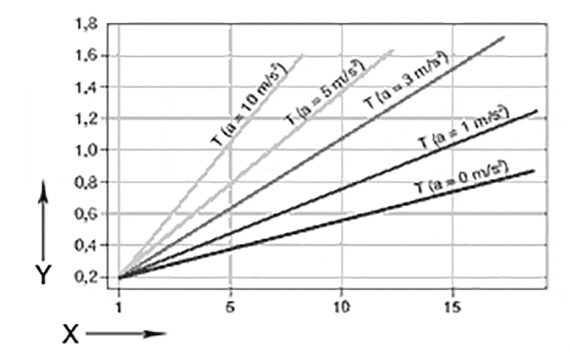
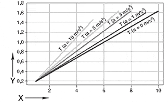
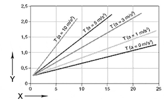
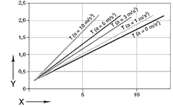
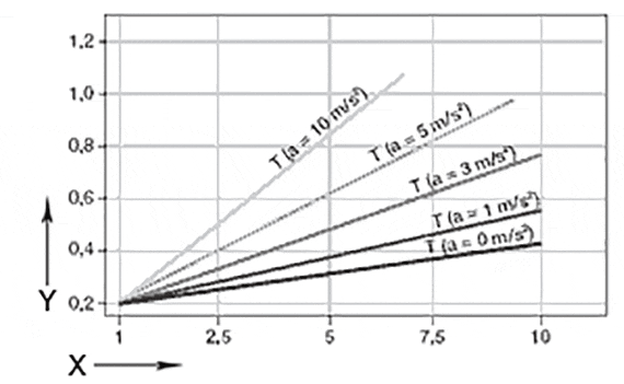
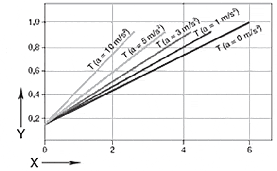
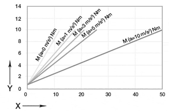
drylin® ZLW - Toothed belt axis - Drive torque and load


Drive torque and fill weight of the ZLW-1040/1080

Required drive torque*
Horizontal orientation– ZLW-1040/1080, Version basic 02

Required drive torque*
Vertical orientation – ZLW-1040/1080, Version basic 02

X = Load capacity[kg]
Y = drive torque [Nm]
X = Load capacity[kg]
Y = drive torque [Nm]

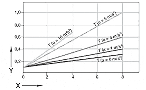
Required drive torque*
horizontal orientation – ZLW-1040/1080, Version standard 02

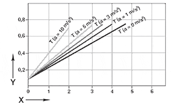
Required drive torque*
Vertical orientation – ZLW-1040/1080, Version standard 02

X = Load capacity[kg]
Y = drive torque [Nm]
X = Load capacity[kg]
Y = drive torque [Nm]
* Supposition: The moving mass is located in a circumscribed circle with a max. R = 100 mm to the middle of the rail, max. permissible torque, version 01: 1.3 Nm, a= 0 m/s² ; version 02: 2.4 Nm, a= 0 m/s²; constant drive without nominal value acceleration.

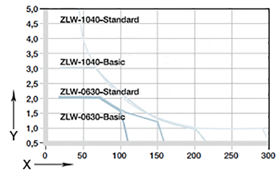
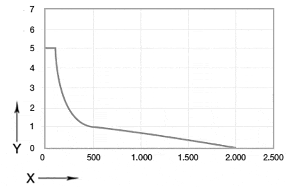
Maximum load in comparison
ZLW-0630 and ZLW-1040/1080

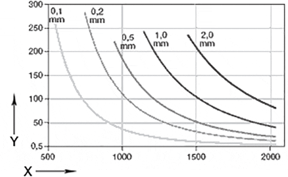
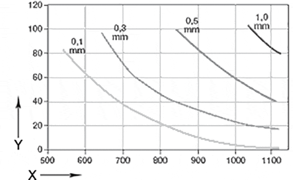
Sag between unsupported end blocks
ZLW-1040/1080, Version basic 02 and standard 02.

X = load of the carriage [N]
Y = speed of the carriage [m/s]

The diagram accounts for the sum of all forces active on the carriage. ED = On-time
X = Support lenght [mm]
Y = load [N]

Sag permissible up to maximum 2 mm .

Drive torque and load of the ZLW-0630

Required drive torque*
Installation position horizontal - ZLW-0630, basic version 02

Required drive torque*
Installation position vertical - ZLW-0630, basic version 02

X = Load capacity[kg]
Y = drive torque [Nm]
X = Load capacity[kg]
Y = drive torque [Nm]

Required drive torque*
Installation position horizontal - ZLW-0630, standard version 02

Required drive torque*
Installation position vertical - ZLW-0630, standard version 02

X = Load capacity[kg]
Y = drive torque [Nm]
X = Load capacity[kg]
Y = drive torque [Nm]
* Supposition: The mass to be moved is in a circumscribed circle with a max. R = 100 mm to the centre of the guide rail, max. permitted torque, version 01: 1.3 Nm, a= 0 m/s² ; version 02: 2.4 Nm, a= 0 m/s²; constant drive without nominal value acceleration.

Maximum load in comparison
ZLW-0630 and ZLW-1040/1080

Bending under load based on the width between supports
ZLW-0630, basic version 02 and standard 02

X = load of the carriage [N]
Y = speed of the carriage [m/s]

The diagram accounts for the sum of all forces active on the carriage. ED = On-time
X = Support lenght [mm]
Y = load [N]

Sag permissible up to maximum 2 mm .

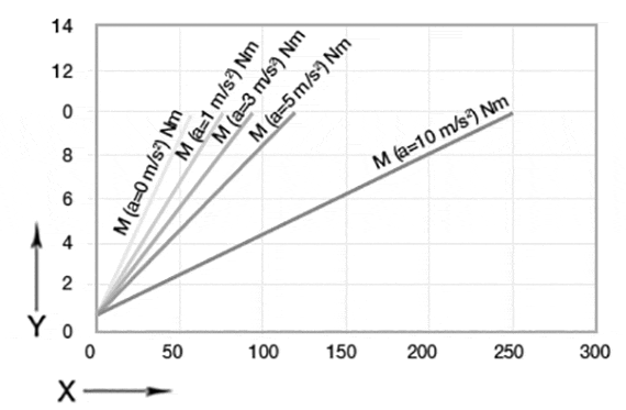
Drive torque and fill weight of the ZLW-1660

Required drive torque*
horizontal orientation – ZLW-1660, Version standard 02

Required drive torque*
Vertical orientation – ZLW-1660, Version standard 02

Required drive torque horizontal X = payload [kg]
Y = torque [Nm]
Required drive torque vertical X = payload [kg]
Y = torque [Nm]
*Assumption: the moving mass is located in a circumscribed circle with a Max. R = 100 mm to the middle of the guiding rail, max. permissible torque Version 01: 1.3 Nm, a = 0 m/s²; Version 02: 2.4 Nm, a = 0 m/s²; constant drive without nominal acceleration value

Maximum load,
horizontal orientation; the diagram accounts for the sum of all forces active on the carriage.

Max. load X = Carriage load[N]
Y = Carriage speed [m/s]
 

Consulta

Teremos muito prazer em esclarecer as suas dúvidas e perguntas pessoalmente

Envio e consulta

Pessoalmente:

De segunda à sexta das 7:30 às 17:18

Online:

24h