Alterar idioma :
drylin® T - Dados técnicos

drylin® - Dados técnicos
| barra deslizante | |
|---|---|
| Material | Alumínio, seção extrudada |
| Material | AlMgSi0,5 |
| Revestimento | Alumínio anodizado duro, 50 µm |
| Dureza | 500 HV |
| Carro deslizante | |
|---|---|
| Estrutura de base | Alumínio, seção extrudada |
| Material | AlMgSi0,5 |
| Revestimento | Anodizado, E6/EV1 |
| Elementos deslizantes | Material de mancal liso livre de manutenção iglidur® J |
| Parafusos, molas | Aço inoxidável |
| Tampa | plástico (TW-01/TWA-01), aço (TW-02) |
| Máx. Velocidade da superfície | 15 m/s |
| Faixa de temperatura | -40 °C a +90 °C |
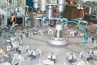
drylin® T em uso no setor de embalagens
Especificação especial
- Devido à baixa inércia e à ausência de componentes rolantes, são possíveis altas acelerações e, em curto prazo, velocidades extremas de até 30 m/s
- Os trilhos de guia linear drylin® T funcionam a seco e, portanto, não são sensíveis à sujeira. As partículas de sujeira não podem ser incorporadas aos lubrificantes
- Particularmente adequado para uso em tecnologia alimentícia, médica e de salas limpas, pois nenhum lubrificante é liberado no ambiente.
- A resistência à corrosão permite que os trilhos de guia linear drylin® T sejam usados debaixo d'água
- Limpeza fácil com alta pressão
- Baixa vibração e muito silencioso
- O emparelhamento dos parceiros deslizantes de alumínio anodizado e iglidur® J tem um torque de ruptura particularmente baixo
- O drylin® T pode ser combinado e intercambiado com guias lineares de rolamento de esferas padrão
- Observe que essa é uma superfície técnica. Dependendo da espessura do revestimento, as variações de cor óptica não podem ser evitadas
drylin® T - capacidade de carga permissível, estática
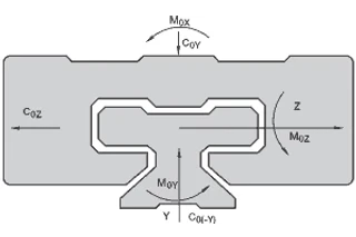
Diagrama 01: Marcação das direções
| Tipo | C0Y [kN] | C0(-Y) [kN] | C0Z [kN] | M0X [Nm] | M0Y [Nm] | M0Z [Nm] |
|---|---|---|---|---|---|---|
| 04-07 | 0,2 | 0,2 | 0,1 | 1,2 | 0,6 | 0,6 |
| 04-09 | 0,48 | 0,48 | 0,24 | 3,4 | 1,8 | 1,8 |
| 04-12 | 0,96 | 0,96 | 0,48 | 9,2 | 4,4 | 4,4 |
| 04-15 | 1,4 | 1,4 | 0,7 | 17 | 8 | 8 |
| 01-15 | 4 | 4 | 2 | 32 | 25 | 25 |
| 01-20 | 7,4 | 7,4 | 3,7 | 85 | 45 | 45 |
| 01-25 | 10 | 10 | 5 | 125 | 65 | 65 |
| 01-30 | 14 | 14 | 7 | 200 | 100 | 100 |
drylin® T - capacidade de carga permissível, dinâmica
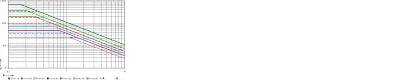
X = velocidade v [m/s]
Y = carga F [N]
A = direção y
B = direção z
diagrama. 02: drylin® T - capacidade de carga permissível, dinâmica
Seu contato técnico
Será um prazer responder suas perguntas pessoalmente!

Horário de funcionamento:
De segunda a sexta-feira, das 8:00 às 17:00 horas.
Online:
24h